Saturday 20 October 2012

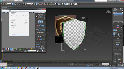
Shield from a reference image


Shield:

Open image in PhotoShop- Work with image which is symmetrical

Look up size of image

Take height and divide by 300

Times number by 48

Go to front wireframe view and enlarge the screen

Create a plane length 60 and width 48

Right click Wireframe word in the top left of the box and select shaded


Press G key to get rid of grid

Press M to open material editor and select modes – Compact- go to Maps- diffuse colour- none- bitmap- open image

Move image back

Right click front shaded window (actual image) and select object properties- Tick freeze and untick Shaded grey 


Enlarge view- create another plane- same size- right click- object properties- check see-through 


Convert- editable poly- vertex mode


Create a selection over a line of dots (vertical) and use the scale tool to shape them to the shield

Use move tool with vectors

Go to the other view, which shows all 4 screens and go to Border mode (right hand menu- modify)- click on an edge and use the shift button and the move tool- pull the Y axis backwards to give the shield some depth (Press F4 to show lines)


 Object Properties- uncheck See-through

Uncheck the plus sign for editable poly- modify list- FFD (Free form defamation 4 x 4 x 4)

Go to plus (right hand menu) for FFD 4x4x4 and select control points- draw a selection and shape accordingly (in this case pull the 4 middle points outwards to create curve to the shield)


When happy convert to editable poly 


Unwrap UVW- open UV editor 


Select red cube (poly mode) in UV editor
Press Ctrl and select the individual polys for the front of the shield, Press shift and select a poly to unselect it 

Mapping- Flatten mapping (gives view of the shield in UV editor) 


Ctrl and I to invert selection- Mapping- Unfold mapping 


Load in PhotoShop- drag the shield picture onto the shield template and match up the grid

Ctrl and J to copy background layer and place at the top

Fill in white a new layer and put it underneath the shield reference image

 PhotoShop:
Put a wood texture picture onto the long strip (which surrounds the shield)


Ensure that the grid on the top layer is turned off before applying the texture in Max by clicking the eye icon
Go Back into Max and press M to open material editor- Map- diffuse colour- bitmap- open photoshop template and drag the material onto the shield, then press the checkered button with the light bulb to see the texture 


To smooth the shape: Right click- convert to editable poly- drop down list for editable poly- select Polygon
Ctrl and A to select all of the shield- Modify- Go down to ‘Polygon: Smoothing Groups’ and select Auto Smooth
When you press the teapot to render the shield the edges should appear to be smoothed 


Click the drop down arrow (right hand menu) and go to Flatten image
Shield Spec:
Press Ctrl + Shift + N to create a new layer on top (as a back-up)
On the new layer (one just created) Go to image- Adjustments- De-saturate to make it black and white
Image- Adjustments- Levels- adjust the levels so that the highlights stand out (where the light is reflecting show up really well)
Image- Adjustments- Brightness/contrast- adjust the contrast to make the wood dark and the metal bright 


Bump Map:
Press Ctrl + Shift + N to create a new layer on top
On the new layer (one just created) Go to image- Adjustments- De-saturate to make it black and white
Image- Adjustments- Brightness/contrast- adjust the contrast to make the middle part of the shield stand out


Shield Spec Colour:
Press Ctrl + Shift + N to create a new layer
On the new layer (one just created) go to image- Adjustments- De-saturate to make it black and white
Press Ctrl + J to copy the background layer and move it to the top
On the top layer (background copy) select colour from the drop down menu (menu to the right)


In Max- Press M to bring up material editor- open the material which you already have on the shield
Go to Maps- check specular colour- Press none- select the photoshop file called Shield Spec colour (it should be a gold tinted shield
Check Specular Level- Press none- select the Photoshop file called Shield Spec (it should have very dark coloured wood)
Check Bump- Press none- select the Photoshop file called Bump Map (it should have a black and white lighter coloured shield) 


                                                              Before                        After


Sunday 14 October 2012

Making a crate


Crate:

Box, 48, 48, 48 and then create- by keyboard entry

Right click- convert to editable poly (bottom option)

Select red box icon under ‘selection’  (right menu) and crtl and a to select all faces

Inset- by polygon- value 4

Make sure all selected (ctrl and select faces individually if not already selected), DO NOT use Ctrl and A to select the faces, they have to be selected individually!

Click extrude (the box next to it) in the right hand menu- value -4

Click off to see the extrusion has worked correctly 

Click square next to editable poly so that it disppears

Unwrap UVW

Open UV editor button

Select red cube at bottom of the UV editor window

Ctrl and A to select all of the faces

Mapping- flatten mapping- change values accordingly- press ok

 Make sure you’re not in editable poly mode! 
Drag all faces out of area

Move one of the squares /faces (any one) into your work area

Press grey box to select whole cube, with edges

Select the cubes with edges with the grey cube button on and drag across

Click each edge and right click and press stitch

Deselect the grey cube and select the red cube (polys), select each polly edge inidivually, right click and select break

Deselect the red cube and select the triangle to select the edges, right click and select stitch to join them together (make sure any connections have been broken)  

Reclick checkerpattern (checker)

Don’t stitch the corners together, it makes the material texture distorted

From here follow the steps which we learnt last time 

Mapping- render UVW template 

Then save it and go into Photoshop to add texture to the template 

Go back into 3Ds Max and press M to bring up the material editor


After the texture has been applied it should look something like this: 


To apply texture to only certain sides:

Go to the uv editor

Select a face (all of it)- right click- select copy- select another face- right click and select paste: this copies the co-ordinates of the previous face and stacks them on top of each other, carry on doing this until theres only one square, then scale the square to fit the work area 


Do the same for this crate template as for the previous one:


Sunday 7 October 2012

Wednesday 3rd October- Applying Textures, Light and Shadow


Notes: 3D Modelling

Applying textures:

Create a box which is 48 by 48 by 48, do this by going to the right hand panel, selecting the create tool and typing these values in then click the 'Create' button

Go to modify and select unwrap UVW (acts as the axis) 

Click on the Open UV Editor… button to the right hand side of the screen

Click on the red cube button to select a side of the cube, once selected it will turn red

Pull the red grid to different areas and this will create a square for each side of the shape (you don't need to do this but you can)

Click CheckerPattern in the top right drop down menu to create a texture

Use Crl + A to make the checkered pattern larger and to Select all of the faces

To unfold the shape go to ‘mapping’ then ‘unfold mapping’, this will allow you to see how the shape is formed and will make it easier when trying to apply textures

Click Angle snap Toggle (in the main window) and rotate to get the top face of the cube at the top of the window

Click the grey cube at the bottom of the window to select the entire template

Go to Tools (in editor) - render UVW template and alter the resolution accordingly

Save as a JPEG and Zoom out to ensure all lines are intact

Open the JPEG image of the template which you just created in Photoshop 

Also open up all the images for the textures which you want to apply to your shape

Label up where the sections of the template are located (Photoshop) by going back into 3ds Max to check where each section of the cube is located on the template 

To do this use the text tool on Photoshop and write in where each section is on each square

Select all the text layers by clicking on them and holding down the shift key and select merge layers from the drop down arrow located just above within the same panel

Click on the background layer (if its locked double click it to unlock it) and click Ctrl and J to copy layer

Move the copied background layer to the top layer

Go to Image (located along the top of the window)- Select image- adjustments- desaturate 

Click Ctrl and I to make it black and white (invert the layer)

Go to the Drop down menu on the right panel- select multiply

Go to View (at the top of the window)  and select Rulers to view the rulers

Go to View- Snap- then uncheck to make line move smoothly

Place the ruler lines to match up with each line on the template

Go to  one of the textures and Grab (using the arrow) and ctrl A to select all of the texture, then press ctrl and C to copy

Select text layer and control and V to paste the image

Free transform to shape exactly to the template size

To rotate the shape you can select it (if its not already selected) and then hover your mouse over one of the corners, you should see a curved arrow symbol allowing you to rotate


Go to Edit- transform- warp whilst holding down shift to match up the details of the shape with other details which might continue around it. 

You can also alter the brightness, contrasts levels, colours ect to make the texture look more realistic, if you select all of the layers of texture have been merged together then when you change one of these levels it will be applied to all of the textures. 

Save it as a Photoshop document

Go back into 3ds Max- Click M-  Modes - Compact

Go to Maps- defuse colour- none

Select bitmap- select file- go back to maps

Unwrap UVW- Collapse All

Change map 1. to map default

Right click the snaps toggle and change the numbers to 8 and 16

Drag it onto the model and it should go grey

Click the Checkerboard with the light bulb to show the material

Hold the shift button and drag to copy

The button with a teapot icon on it located at the top of the window will render it

Right click the UV Modifier and Collapse to, a warning will come up saying Do this as a final change as it cannot be undone, check yes to the warning

Right click the snaps toggle and press option, change the grid space to 8 and the major lines to 16

Press 7 to bring up a poly count

Create a plane to do a floor

Maps- change tiling to change size of the texture itself

Hold down the hand and select the feet icon in the bottom right hand corner to get a first person view

Lights and Shadows:
Go to Create- Lights- Standard- Target Spot

Drag the light to move the position

Hold shift to duplicate the light

With the light selected- modify (blue arc)

Check on Spot

Check on Shadows

Intensity/colour/attenuation:

You can change the colour of the light (too much colour can make the light look unrealistic)

The Multiplier- alters brightness

Spotlight Parameters- Alter how far the light goes

Shadow Parameters:

You can change the colour of the shadow- grey is the most realistic colour

Dens. (density)- 0.7 for a realistic shadow  (alters how strong the shadow which has been cast is)

Add Effects:

Render the image with the tea pot icon- press the jellybeans shaped icon to duplicate the window

Open the material editor by pressing M 

Select material

Go to Default

Check Specular Level and Bump (Bump reflects the light from the surface)

By doing this you can experiment with different effects and see them more clearly without doing it on the main application, so you won't need to undo it if something goes wrong but you can still see what the effects do. 

Wednesday 26th September

As some people hadn't used the programme 3ds Max before or had experience in similar programmes but with different layouts we were first taught the very basics of the software and then experimented with what we'd learnt. 


We learnt that 16 units is the equivalent of 1 foot, so these are the numbers which we will be using: 1, 2, 4, 8, 16, 32, 64, 128, 256, 512, 1021, 2048

Here are some of actions which i learnt the programme can perform: 

- Hold shift and drag to duplicate a shape 

- The symbol which the arrow is pointing to snaps shapes together and can change the angle


- F4: shows the lines of the shape 

- The blue arc shaped icon in the right hand panel is used to Modify shapes 

- If you go to Modify then Parameters you can pick segments of the shape 

- Chafer is a tool which rounds the edges of shapes 

- Extrude is a tool which pulls the shape out/in

- Right Click a shape then go to Convert to and pick Editable Mesh or Editable Poly to change the shape permanently.