Sunday 2 December 2012

Sword


Create a cylinder with 6 height segments and then use the scale tool to squash it into a handle shape

Use inset by right clicking- then pick the amount and press the green tick

Using the scale tool pull on the z axis 


Using the edge tool select the middle horizontal line and press loop- tick soft selection in the right menu and adjust the fallout to adjust the degree that the shape is altered by from the middle

Using polygon mode select the very top of the handle and Inset the top of the handle to create a guard

Click on one of the vertical edges at the very top and select ring and then press polygon mode


Use the bevel tool and group by local to pull out the selection and create a guard- use the selection tool and pull up the z axis to shape the guard 


Go down to polygon smoothing groups in the right menu and in polygon mode select a polygon and then ctrl and A- click clear all

Drag a selection over the handle only and click on the smoothing group 1

Select the bottom bevel and press alt and left click to deselect the very bottom and then give it a smoothing group of 2 


Select underneath the guard at the top and in polygon mode and give it a smoothing group of 2, this different smoothing group from the handle makes it stand out and become more defined when the light hits it from the other parts of the handle 


In polygon mode select a segment, hold shift and click another segment to ring the selection quickly

Do the same for the rest of the guard- using a smoothing group of 1 for the outside rim and 2 for the inside of it- they have to be different smoothing groups if the parts are touching otherwise they blend into one, losing the effect of the shadow 


Go to the modify tool and select the shapes tab, go to the line tool and create a sword shape about 6 units long

Right click on the line and convert it to an editable poly 


Go to extrude and make the height very high, then in polygon mode delete the end to make it hollow

In vertex mode select the 4 points of the sword which create a rectangle and not the pointed part- then click bridge and pull them together

Select the first 2 vertexes down the face of the sword, right click and the use the weld tool, getting them as close together as possible

Using edge mode select the middle of the sword, right click and select connect- use 8-10 segments 


In vertex mode figure out which end is the pointed end and then in the left wireframe view start to move the vertexes around so that it looks more like a sword shape- do this until you’re happy with the shape of the blade- try to make the vertexes line up 


Go to edge mode and select one of the middle edges then press loop, if only one side loops press ctrl and select an edge on the other side then press loop again- pull out the sword on the x axis (red line) until you’re satisfied with the width 


Highlight the bottom sections using polygon mode and give them a smoothing group of 3 on one side of the sword then do the same for the other side but changing the group to 4
Do the top sections with a smoothing group of 1 and the other side a smoothing group of 2 


Unwrap the handle- select all of the handle apart from the guard and the bottom bevel using the polygon tool- click on the cylinder projection and then click fit and center

Click on the Y if your sword is facing in the direction of the y axis

Unselect the cylinder projection 


Sunday 18 November 2012

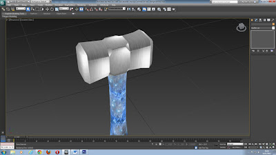
Wednesday 14th November: Sledge hammer


Create a cylinder

Height: 16

Radius: 4

Parameters- change the sides to 10- if there’s no change then do this in the modify tab and change the sides in there instead

Press F4 to see the edges  


Turn the height segments down to 3 and the cap segments down to 1 


Drag the X axis (red line) inwards to make it look more like the handle of a sledgehammer
One done-  right click and convert to editable poly  


Go into edge mode- red triangle icon and select one of the lines going around the shape- click loop so that it wraps all the way around the model

Press and hold ctrl- select the other line going horizontally just beneath it and press loop again
Grab the Y axis and pull inwards to make it look more like a handle shape

Press the red cube tool and click the shape to select the whole shape then adjust it on the Y axis until you’re happy with the shape 


Create a box over the top using the top wireframe view look at how the box fits over the top of the handle

Select the handle and go to the align tool, click center on both settings and apply to put the hammer head in the middle of the handle  


Check Z position and select Maximum on both settings and apply, the head should be at the top 

If you go into polygon mode and select either side face of the hammer then use the scale tool to make either end wider

When happy right click and convert the head to an  editable poly


Select the two top edges- the 1st segment and the 3rd segment and then press Ring 


Right click and select chamfer to get a hammer head shape- the size will be dependent on the size of the head- I set mine to 0.66 and the bottom option to around 2

Using polygon mode select each end of the head and right click- select the small box next to Inset and pick an amount, usually 0.3 works well- ensure that it is grouped by polygon and not by Group


In this view (3D view) right click the word which says Realistic and click consistent colours then go to Lighting and Shadows- untick shadows 


Select the hammer head and open UVW editor

Go to polygon mode in the UV window

Select the middle polygon on the inverted face and press the grow selection button which is a blue box with a little grey square in the bottom left corner and a plus sign at the top right corner, this will select everything in that face, even the outside edges. 


In the max window go to projection and select the icon which resembles a plane, then deselect the icon after to ensure that you can click other things.  Then move this to one side in the UV editor window and do the same for the other face. 


Draw a selection box around the remaining polys and select the cylinder tool from projection- then click to the Y button under align options

Select the faces individually (separate boxes) and reduce the size of them with the scale tool
Right click and convert to an editable poly

Repeat the same process for the handle


With the handle selected click on attach under edit geometry and then select the hammerhead; it should turn the same colour as the handle

Click attach again so that you don’t attach anything else


Convert to editable poly and unwrap UVW, then organise all of the shapes so that they fit into the box, making the most out of the given space

Tools- render the UVW template and put in 512, 512 for the resolution, save it as sledgehammer template in JPEG format

Then open it up in Photoshop and pick some textures from the internet, place them on the different areas of the template, go back into Max and open up the material editor- ensure that its in the correct mode- go to maps- then diffuse colour and pick the bitmap which you did in photoshop- press the checkerboard with the lightbulb to see the texture


Sunday 11 November 2012

Tree- Using an Opacity Map


3Ds Max notes:

Put picture of tree into Photoshop


Use as base texture for tree

Press Ctrl and J to add a new layer and work from that one (the background layer acts as a backup copy)


Select wand tool- Make sure contiguous at the top is unticked

Click and press delete to get rid of the background

Ctrl and D to deselect selection

Ctrl and left click the layer

Ctrl, shift and N to create a new layer- on the new layer select the paint bucket tool and ensure that the white colour is selected then click on the tree, this should fill it white

The selection outline should still be showing around the tree


Ctrl and D to deselect

Create a new layer underneath and use the paint bucket tool to fill the background in Black (make sure the black colour is selected- you can use the double arrow next to the colour selection to switch the colours around 


Merge the two layers (the white tree and black background)- Ctrl and click the other layer then right click and select merge layers

Save it as a JPEG- keeping the quality at maximum 


Use the eye tool to hide the black and white tree

Create new layer above background layer- select the colour box and use the dropper tool to select the darkest green on the tree

Fill the background in with the dark green colour

Ensure you’re on the tree layer

Select the burn tool

Change range to highlights or midtones- exposure to 75%  


Go round the outside of the tree to darken it

New layer- select colour from drop down menu where it says normal- select the paint brush tool- same colour as background and go round the outside of the tree to make the outside blend in 


Merge the dark green background layer, the tree layer and the tree outline layer- save the image as tree texture

Go to the black and white tree layer- use the magic wand to select the white tree- go to your background layer- press Ctrl and J- there should now be a tree picture with a blank background
Turn off all other layers 


 Ensure that the transformation controls box is ticked to be able to see the box around your selection (located at the top)

Select the polygon lasso tool- cut out the top of the tree- Ctrl and J to copy onto a new layer- ctrl and J again, then move the dot in the middle down to the bottom of the box and in the centre and rotate it to the right (about 40 degrees)- repeat the process until it looks like a star (a bird’s eye view of a tree)- this will be the top of the tree, but from looking down onto it 


Wand tool on the star tree layer - new layer/ctrl and J- fill it with black (underneath)- deselect the selection and put a white layer underneath- merge the layers

Save it as tree opacity map (top view)

Create a green background and view the green detailed tree top, merge the 2 layers

Save it as tree texture (top view)


Max:

Create a Plane

Length: 128

Width: 93

Length and Width segments (underneath) both needs to be set to 1

Use the angle snap tool and rotate tool to rotate the plane 90 degrees upwards
Press M to open material editor and select the standard button- select multi/sub- object from the menu- press yes to discard old material- it should turn black and have 10 slots


Set the number of slots to 2 by clicking on the Set Number button

Slot 1- click none- select standard from list  


Note: Select default from drop down list to go back to main menu and switch between materials

Go to maps- diffuse colour- none- bitmap- tree texture

Maps- opacity- none- bitmap- tree texture opacity map


Go to default level- drag the material onto your plane- click on the material button in the slot list and click the checkered board with the light bulb to show the material 


In the material editor- in the material itself (1st slot) tick 2 sided so that when the tree is rendered you can view both sides

Name your material tree side by clicking in the grey box with the name material…  (it should have a number next to it) to distinguish the difference between your material and the home menu 

Select the rotate tool and the angle snaps- hold down shift and rotate it about 45 degrees- select copy and type in 4- this makes the tree more dimensional 


Ctrl and A to select all- right click- convert to editable poly- select one of the sides- in edit geometry click on the small box next to attach- click on one of the planes on the list and hold down Ctrl selecting all of them individually then click attach 


Go to the top view viewport- select create- cylinder- set the:

Height: 0

Cap segments: 3

Sides: 12

Make the cylinder about the same size as your tree    


Pull the circle up away from the tree and right click- isolate selection- right click- convert to editable poly- click on red dots to go to vertex mode (press F4 to bring up the grid)- pull up the middle to make a point

Then use the selection tool to pull the vertexes downwards creating a cone- experiment until it looks right 


Press Ctrl and A to select all and scroll down the left hand menu- go to Polygon material IDs and set the ID to 2  


Repeat the process for the material- this time selecting the top view- ensure that 2 sides is checked 


Hold shift and pull away to copy the shape, continue this process, then rotate and scale some of the branches/leaves

Create a cylinder and put a wood texture onto it to create a tree trunk